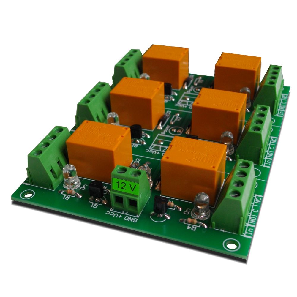

GPIO0 pin for relay control (high level status) Īs the assembly devices are not energized at the same values as the table lamp, a more appropriate power supply is required.Īlthough the ESP-01 module requires a different supply voltage than the Relay module, a different power supply will not be required because the ESP-01 module is energized directly through the Relay module (see image below).Īs can be seen easily, the ESP-01 module has many advantages, but in contrast to other card models already mentioned before, this module does not allow connecting directly to a computer to load the programming code.įor this reason, an adapter device is needed to guarantee this connectivity, if possible through the USB plug (see image below).ĮSP-01 USB adapter module specifications:.This module is designed to work together with the ESP-01 module and also has a very easy to use 8 pin connector (see data sheet below). Digital I/O pins (PWM) - GPIO0 and GPIO2 Īnother module that is also very useful when creating projects in IoT systems is the Relay module.SPI, UART and SDIO communication protocols.Tensilica Xtensa integrated CPU of low power and 32 bits.This time the main device will be the ESP8266 ESP-01 module, which will control and manage all the assembly resources. In the last tutorial, the ESP8266 ESP-01 module was used only as communication device, receiving and transmitting only Wi-Fi data and not as main assembly equipment.Īrduino Tutorial - Blynk Motor Speed Control ESP8266: In the previous tutorials we used several different types of Arduino boards and these were always the main devices of the assembly and contained the programming code, controlling and managing all the features. This equipment stands out for its small size, low price and versatility.

This physical device will have a relay that will control a simple lighting system and this relay will be connected to a very small and simple Wi-Fi control device, this device is the ESP8266 ESP-01 module (see datasheet below). With this application we can use interfaces that control and view the data generated from a physical device remotely, just have that device and a smartphone connected to the Internet. This App has already been mentioned in previous tutorials, but this season we'll describe in detail the most important features of each of its widgets. To create these systems we will use the Blynk App designed for IoT systems and it is a very easy and intuitive application to work with (See the image above). Welcome to another tutorial on our channel, this is the first tutorial of this season that will be dedicated to IoT systems, here we will describe some of the features and functionalities of the devices used in this type of systems.


 0 kommentar(er)
